Return to flip book view
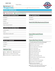
Project Name Site Survey in 1 2 3 Project Info Structural Info Electrical Info PROJECT INFORMATION ASTERISK COLOR CODE KEY Required Field Account Preference HOMEOWNER INFORMATION AHJ INFORMATION First Name AHJ Name Last Name Utility Name Address Special AHJ Utility Requirements If Known City State Zip Project s Assessor s Parcel CONTRACTOR INFORMATION Company Name Phone Address Street City State Zip Snow Wind Loads If Known Snow Load Wind Load License Numbers Project Site Photos Checklist PROJECT MANAGER Photos will be used to understand site conditions and project site and are essential to generate an accurate permit package First Name Utility Meter Location Zoomed out View Last Name Main Service Panel Location Phone Close up of Main Service Panel Label Close up of Main Breaker Application Type Please select the appropriate racking application types Tilt Up Flush Mount Integrated Racking Flat Roof Use 2b on pages 8 and 9 instead Ground Mount Use 2c on pages 10 and 11 instead Close up of Main Breaker Label Sub Panel Main Breaker If used Sub Panel Location If used Subpanel Location If used Close up of Sub Panel Breaker Label Proposed Inverter Location Zoomed out View Array Location s if possible Entire Roof with Obstructions If possible Ground Mount Location If applicable Rafter Truss Size and Spacing Show tape mesure in photo if possible Attic Space Show existing roof rafter truss for each roof structure Show tape measure if possible GREENLANCER COM 866 436 1440 Sales GreenLancer com 1
Site Survey in 1 2 3 Project Info Pitched Roof Structural Info Electrical Info ARRAY 1 PITCHED ROOF APPLICATIONS PITCHED ROOF STRUCTURAL INFO RACKING INFO Roof Material Attachment Type Please select the appropriate roof material from the options below Flashed L Foot Tile Hook Asphalt shingles Standing Seam Metal Integrated intoRacking Corrugated Metal Clay S Tile Corrubracket Flat Tile Rubber Membrane Wave Tile Other ____________ Standoff Standing Seam Clamp Other _____________ Racking Manufacturer Wood Shake Layers of Roof Material One Racking Model Two Attachment Manufacturer Structure Type Please select the appropriate Structure Type from the options below Truss Wood Knee Wall Collar Tie Metal Beam Supported Collar Tie Wood Interior bearing wall Wood Single Span Rafter Wood Purlins Wood Supported Strut Knee Wall Steel Frame 2x6 2x8 2x10 Other _______________ Rafter Spacing Please select the typical distance between each rafter in inches 12 14 Maximum Rail Span Please select the default maximum distance between mounting points accross the rail layout used for this project 16 Rafter Size 2x4 Attachment Model 16 24 48 24 32 48 72 96 Other ______ Pitch Degrees Azimuth s Other _________ Roof Structure Measurements A _______________ B _______________ GREENLANCER COM 866 436 1440 Sales GreenLancer com 2
ARRAY 2 PITCHED ROOF APPLICATIONS Only if roof structure is different PITCHED ROOF STRUCTURAL INFO RACKING INFO Roof Material Attachment Type Please select the appropriate roof material from the options below Flashed L Foot Tile Hook Asphalt shingles Standing Seam Metal Integrated intoRacking Corrugated Metal Clay S Tile Corrubracket Flat Tile Rubber Membrane Wave Tile Other ____________ Standoff Standing Seam Clamp Other _____________ Racking Manufacturer Wood Shake Layers of Roof Material One Racking Model Two Attachment Manufacturer Structure Type Please select the appropriate Structure Type from the options below Truss Wood Knee Wall Collar Tie Metal Beam Supported Collar Tie Wood Interior bearing wall Wood Single Span Rafter Wood Purlins Wood Supported Strut Knee Wall Steel Frame 2x6 2x8 2x10 Other _______________ Rafter Spacing Please select the typical distance between each rafter in inches 12 14 Maximum Rail Span Please select the default maximum distance between mounting points accross the rail layout used for this project 16 Rafter Size 2x4 Attachment Model 16 24 48 24 32 48 72 96 Other ______ Pitch Degrees Azimuth s Other _________ Roof Structure Measurements A _______________ B _______________ GREENLANCER COM 866 436 1440 Sales GreenLancer com 3
Site Survey in 1 2 3 Project Info Structural Info Electrical Info ELECTRICAL INFORMATION NEW EQUIPMENT INFORMATION Inverter Location Please select intended location of inverter and electrical equipment Module Manufacturer Model Number 1 Exterior Interior Module Manufacturer 2 House Garage Barn Pole Mounted Other _________________________________ Model Number Quantity 3 String Micro Manufacturer Model Number Inverter Manufacturer North South East West NE NW SE SW Wire Transition Enclosure Please select the appropriate wire transition enclosure between modules and inverter Model Number Junction Box Soladeck Combiner Box None Quantity Combining AC Circuits Optimizer Manufacturer Model Number If Applicable Select how to combine the inverter s AC outputs Multiple inverters or micros only Soladeck Rooftop Optimizer Manufacturer N AC Panel Board Existing Subpanel Model Number Service AC Disconnect Quantity Typically the utility requires a lockable utility disconnect for the AC output in case of an emergency or service Inverter DC Disconnect Options If Applicable Yes Utilize Integrated DC Disconnect Utility Disconnect Location Utilize Standalone DC Disconnect Rooftop or Ground Array Please describe the Utility Disconnect location Standalone DC Disconnect Location If Used 1 Exterior Interior 2 House Garage Rooftop At Ground Array 1 Exterior Interior 2 House Garage Barn Next to Utility Meter Barn Pole Mounted 3 Other ______________________________________________ 3 No North South East West NE NW SE SW Other ______________________ North South East West NE NW SE SW PV Revenue Meter Is there a PV Revenue Meter The Production meter measures and tracks the production for the solar array Yes GREENLANCER COM 866 436 1440 Sales GreenLancer com Pole Mounted No Net Meter 4
ELECTRICAL INFORMATION Continued Location of PV Meter Interconnection Location Select the location of the PV meter in reference to the AC disconnect Please select the electrical location the tap will occur Between inverter and disconnect Between disconnect and point of interconnection MEP Tap Etc EXISTING EQUIPMENT INFORMATION Meter Main Combo Yes No Existing Main Electrical Panel MEP New Tap Box Existing Meter Automatic Transfer Switch ATS New Sub Panel Existing Sub Panel Renewable Meter Adapter RMA at Meter New Main Electrical Panel Upgrade E xisting Meter Location Main Electrical Panel Rating Write the Bus and main circuit breaker rating 1 Exterior Bus Rating amps 2 MEP Location Are there spaces available in the panel 3 Main Breaker Location Center fed North South East West NE NW SE SW Location of the Pole in relation to the house Bottom fed For pole mounted utility meters and main electrical panels Main Electrical Panel Location Cardinal Direction Please select where the Main Electrical Panel is located Distance 1 Exterior Interior 2 House Garage Barn Pole Mounted Other ______________________________________________ 3 Pole Mounted Other _____________________________ Main Breaker Rating amps Top fed Interior North South East West NE NW SE SW N ew Main Breaker Derating or Panel Upgrade Utility Entrance Overhead Under Ground Existing Electrical Grounding Current or Original Bond of existing electrical system Please select from the options below Ground Rod Ufer Cold Water Pipe Write the new ratings that the main breaker will be derated to Project Notes Special Requirements Bus Rating amps Main Breaker Rating amps Interconnection Strategy Please select the appropriate interconnection strategy from the choices below Panel upgrades or choose Backfeed Breaker Backfeed Breaker Line Side Tap Derate Main Breaker Load Side Tap GREENLANCER COM 866 436 1440 Sales GreenLancer com 5
ELECTRICAL INFORMATION Continued Array 1 2 3 4 5 6 Module Quantity Azimuth Pitch or Tilt Shading Optional Mounting Plane From Sketch Rafting Span s in Feet list as necessary Inverter Mftr Model MPPT of Strings Modules String of Strings Modules String of Strings Modules String of Strings Modules String of Strings Modules String of Strings Modules String 1 2 1 2 1 2 1 2 Please list plan for stringing modules under each array Indicate if arrays are to be combined on a given string Important NOTE If the next selection below String Design is Designer s Discretion then the inverter table above does NOT need to be filled out GREENLANCER COM 866 436 1440 Sales GreenLancer com 6
Survey Sketch A rough sketch or drawing of the solar panel layout on the project residence or site including roof measurements where possible and plan for equipment locations from the provided key This sketch will be used to create the base site plan and array layout I placed the modules on the roof sketch below I DC AC INVERTER UM E UTILITY METER PNL AC PANELBOARD V PV REVENUE METER AC DISCONNECT MEP MAIN ELECTRICAL PANEL DSW DC DISCONNECT JB JUNCTION BOX S M1 MODULE X ROOF OBSTRUCTION I want the designer to place the modules The Sales Sketch is attached as a separate document N W E S GREENLANCER COM 866 436 1440 Sales GreenLancer com 7
Site Survey in 1 2 3 Project Info Flat Roof Structural Info Electrical Info ARRAY 1 FLAT ROOF APPLICATIONS Only if applicable FLAT ROOF STRUCTURAL INFO RACKING INFO Roof Material Racking Manufacturer Please select the appropriate roof material from the options below Rubber Membrane Racking Model Rolled Asphalt Gravel EDPM Attachment Manufacturer Duralast Corrugated Metal Roof Attachment Model Layers of Roof Material One Two Maximum Rail Span Structure Type Please select the appropriate Structure Type from the options below 16 Truss Single Span Rafter Portrait Supported by Wood Beams 32 48 72 96 Other ______ Landscape Tilt s Rafter Beam Size 2x6 24 Module Orientation Supported by Metal Beams 2x4 Please select the default maximum distance between mounting points accross the rail layout used for this project 2x8 2x10 Other _______________ Azimuth s Rafter Beam Spacing Please select the typical distance between each rafter in inches 12 14 16 24 48 Other _________ Roof Structure Measurements A __________________________ GREENLANCER COM 866 436 1440 Sales GreenLancer com 8
ARRAY 2 FLAT ROOF APPLICATIONS Only if flat roof structure is different FLAT ROOF STRUCTURAL INFO RACKING INFO Roof Material Racking Manufacturer Please select the appropriate roof material from the options below Rubber Membrane Racking Model Rolled Asphalt Gravel EDPM Attachment Manufacturer Duralast Corrugated Metal Roof Attachment Model Layers of Roof Material One Two Maximum Rail Span Structure Type Please select the appropriate Structure Type from the options below 16 Truss Single Span Rafter Portrait Supported by Wood Beams 32 48 72 96 Other ______ Landscape Tilt s Rafter Beam Size 2x6 24 Module Orientation Supported by Metal Beams 2x4 Please select the default maximum distance between mounting points accross the rail layout used for this project 2x8 2x10 Other _______________ Azimuth s Rafter Beam Spacing Please select the typical distance between each rafter in inches 12 14 16 24 48 Other _________ Roof Structure Measurements A __________________________ GREENLANCER COM 866 436 1440 Sales GreenLancer com 9
Site Survey in 1 2 3 Project Info Ground Mount Structural Info Electrical Info ARRAY 1 GROUND MOUNT APPLICATIONS Only if applicable GROUND MOUNT STRUCTURAL INFO Total Number of Legs Supports Ground Mount Racking Manufacturer Cross Brace If Applicable None Ground Mount Racking Model Horizontal Diagonal Module Orientation Ground Mount Foundation Portrait Landscape Select the foundation that will be used to secure the poles Quantity of Module Rows Helical Piling Concrete Pad Helical Pile Driven Piling Concrete Pad Driven Pile Quantity of Module Columns Earth Screw Concrete Pad Drill Pour Tilt s Pole Embedment Depth This is how deep in the ground the mounting pole is below grade Azimuth s Footing Diameter Front Clearance This is how wide the footing is in inches This is the clearance from the ground to the front of the array Concrete Depth If Applicable Rear Clearance This is the clearance from the ground to the top of the array Horizontal Support Spacing in Feet East West Please input the horizontal distance between the poles Setback Requirement from the Property Lines in Feet If Applicable Inner Row Support Spacing in Feet North South If Applicable Please input the North South spacing between poles if applicable GREENLANCER COM 866 436 1440 Sales GreenLancer com 10
ARRAY 2 GROUND MOUNT APPLICATIONS Only if ground mount is different GROUND MOUNT STRUCTURAL INFO Ground Mount Racking Manufacturer Module Orientation Portrait Landscape Quantity of Module Rows Ground Mount Racking Model Quantity of Module Columns Ground Mount Foundation Select the foundation that will be used to secure the poles Helical Piling Concrete Pad Helical Pile Driven Piling Concrete Pad Driven Pile Tilt s Azimuth s Earth Screw Concrete Pad Front Clearance Drill Pour This is the clearance from the ground to the front of the array Pole Embedment Depth This is how deep in the ground the mounting pole is below grade Rear Clearance This is the clearance from the ground to the top of the array Footing Diameter This is how wide the footing is in inches Setback Requirement from the Property Lines in Feet If Applicable Concrete Depth If Applicable Horizontal Support Spacing in Feet East West Please input the horizontal distance between the poles Inner Row Support Spacing in Feet North South If Applicable Please input the North South spacing between poles if applicable Total Number of Legs Supports Cross Brace If Applicable None Horizontal Diagonal GREENLANCER COM 866 436 1440 Sales GreenLancer com 11